The finished layout
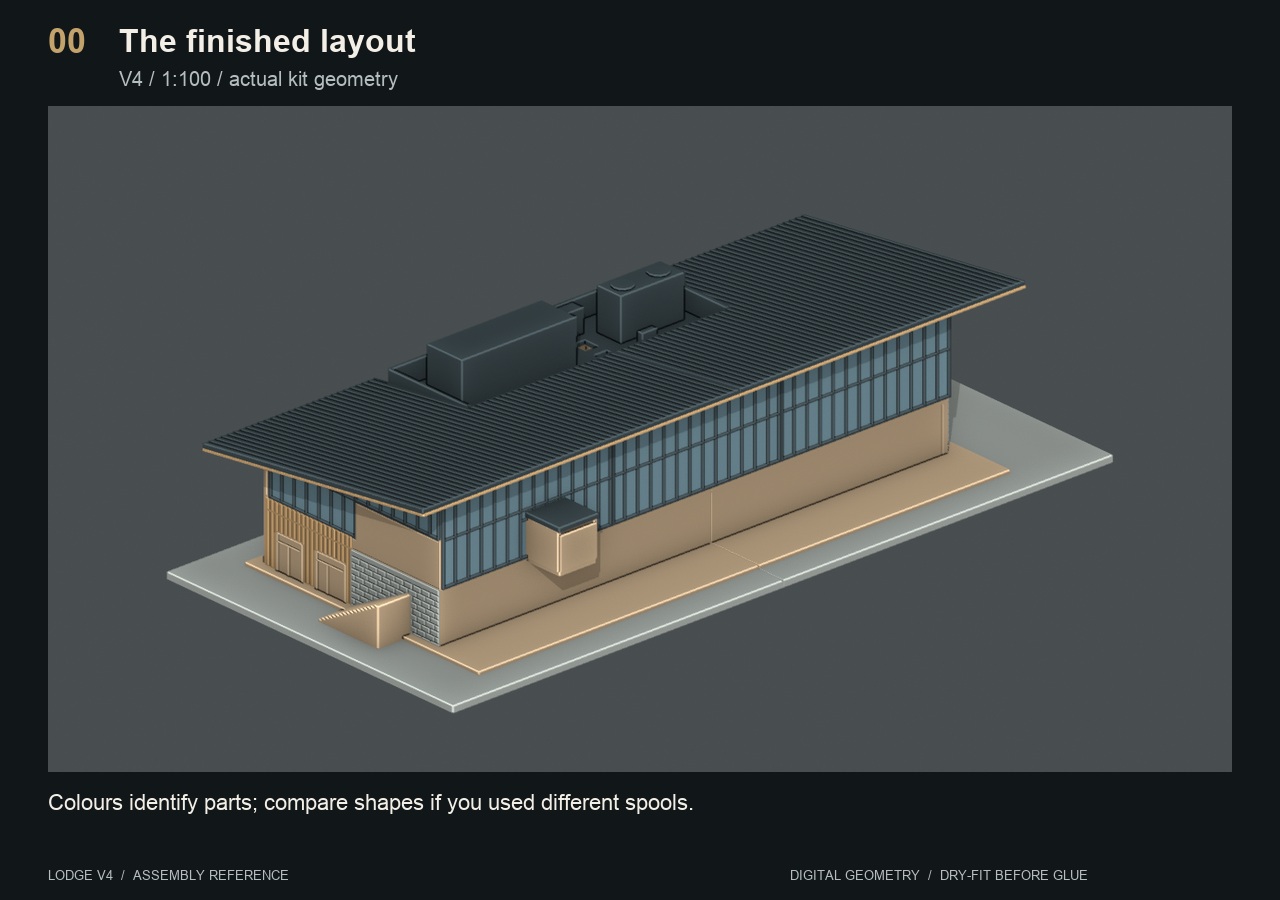
This shows the intended completed V4 layout. Colours identify groups; yours may differ. The animation demonstrates relative positions, not verified insertion paths.
 TALKS WITH TALHAAI CONSTRUCTION TOOLS
SKI LODGE / 1:100
Design the split. Print the parts. Build the model.
01 / THE FILM
Current picture cut with original music. Talha’s narration and on-camera segments will be added next.
The V4 model separates the base, floors, roof, soffit, glazing and finish pieces into manageable print jobs. Each tray uses one material, so the finishes come from the parts themselves.
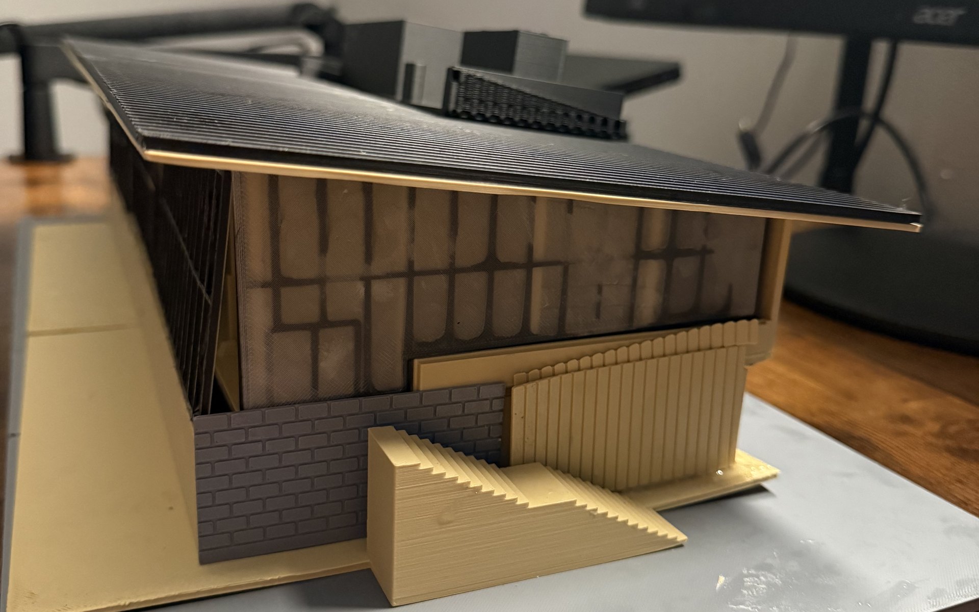
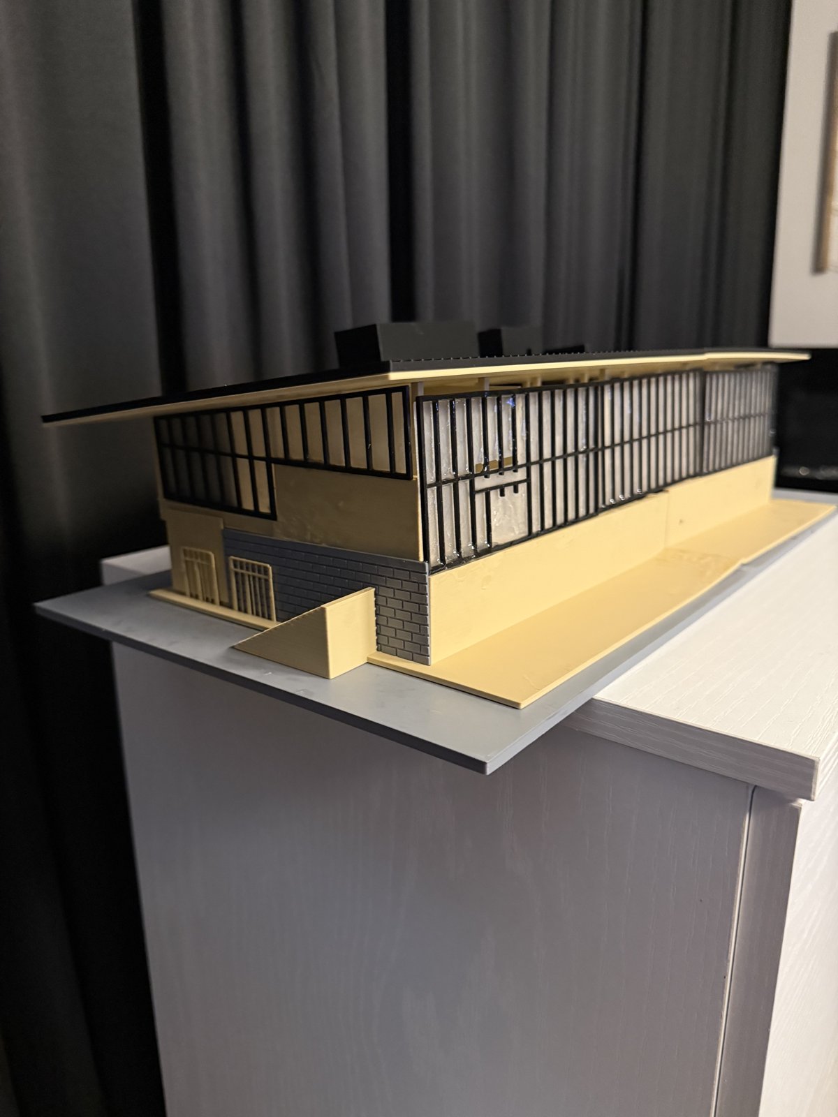
The film follows the real printer timelapses and hands-on assembly, ending with the completed physical model. The guide explains where the pieces belong; the files let you explore the kit yourself.
Follow the build guide →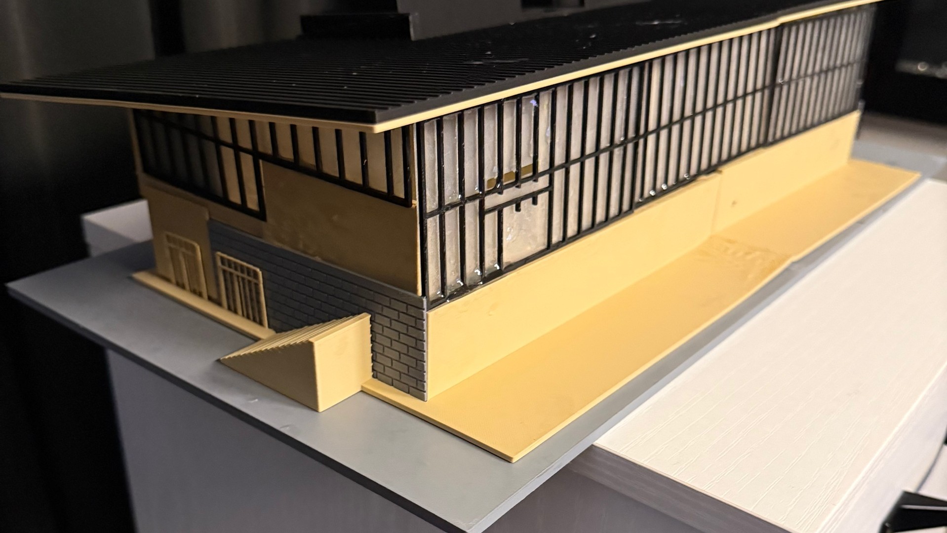
02 / THE BUILD GUIDE
Watch the 68-second silent assembly reference, then follow the illustrated steps and part maps. This guide and the main downloads use the final large V4 kit.
This shows the intended completed V4 layout. Colours identify groups; yours may differ. The animation demonstrates relative positions, not verified insertion paths.
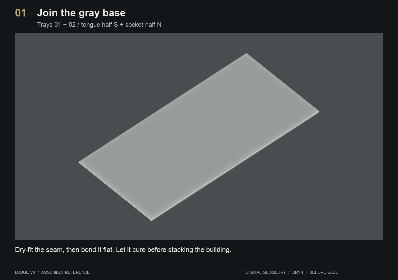
Put both gray plinth halves on a flat table. The S half has the short tongues, and the N half has matching sockets. Slide together without forcing. Check a flat top and a straight seam. After this joint dry-fits flat, bond the broad plinth seam and let the adhesive fully cure before stacking the building. All main modules split on this same line, so the base seam must be secure first. Lift the assembled model under the plinth with both hands, supporting both halves.
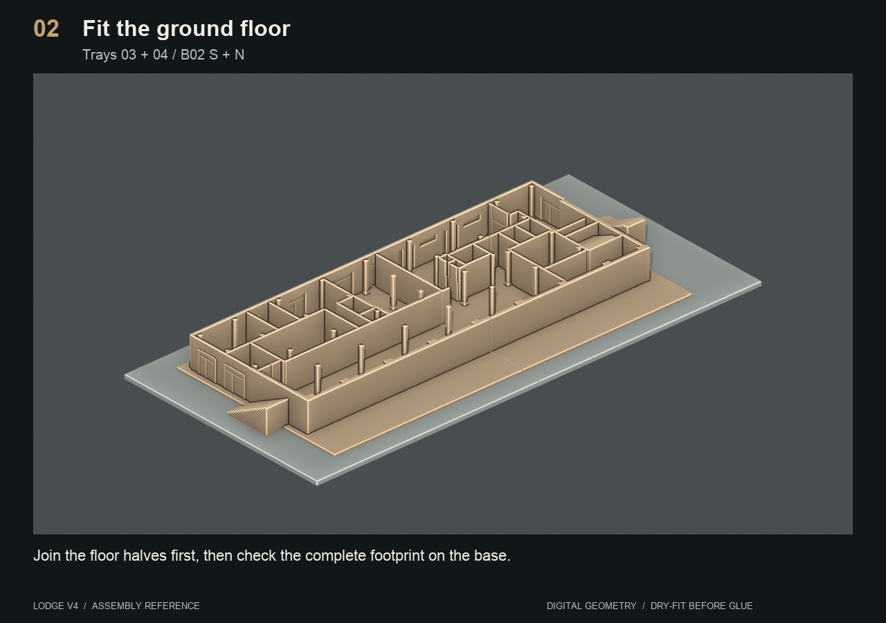
Join the two tan ground-floor halves at their low locating tongues. The walls and floor edges should continue across the middle seam. Set the joined footprint onto the plinth and check even alignment around the base before fixing it down.
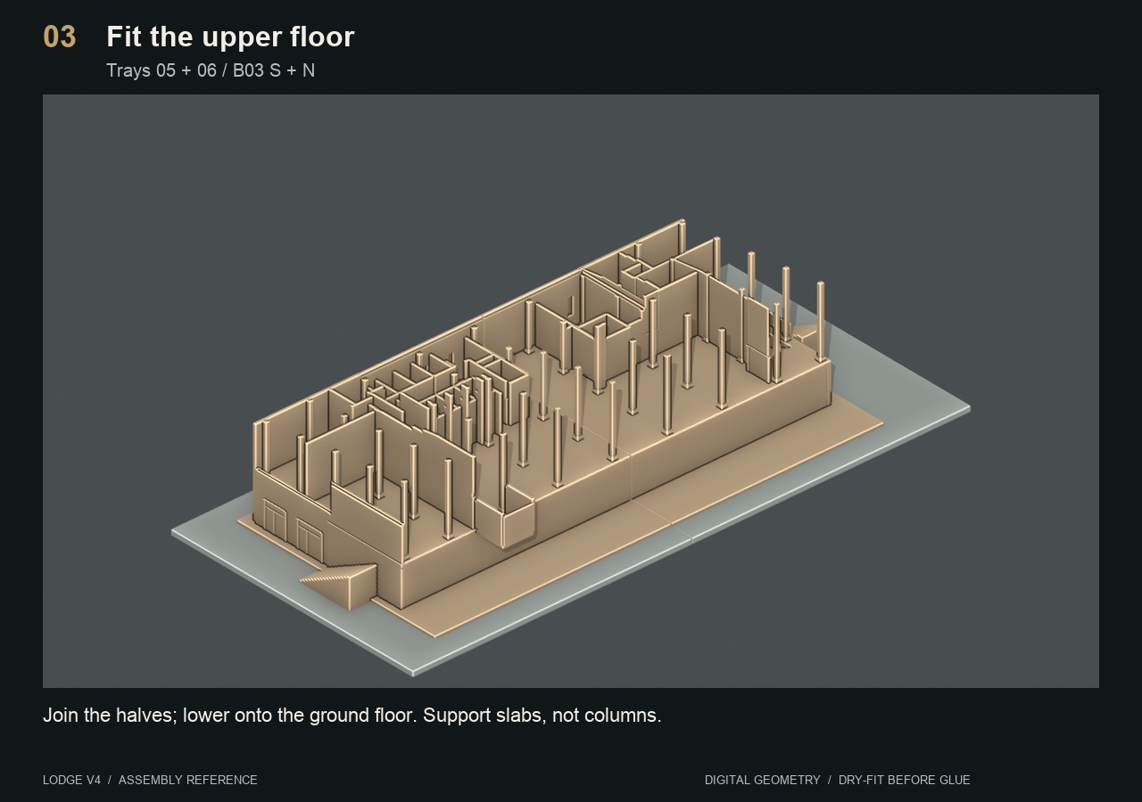
Join the two tan upper-floor halves. Support the underside of the slabs while lowering them onto the ground floor. Line up the outside walls and stairs. If it catches, lift it off and clean only the interfering contact area; never push on the columns.
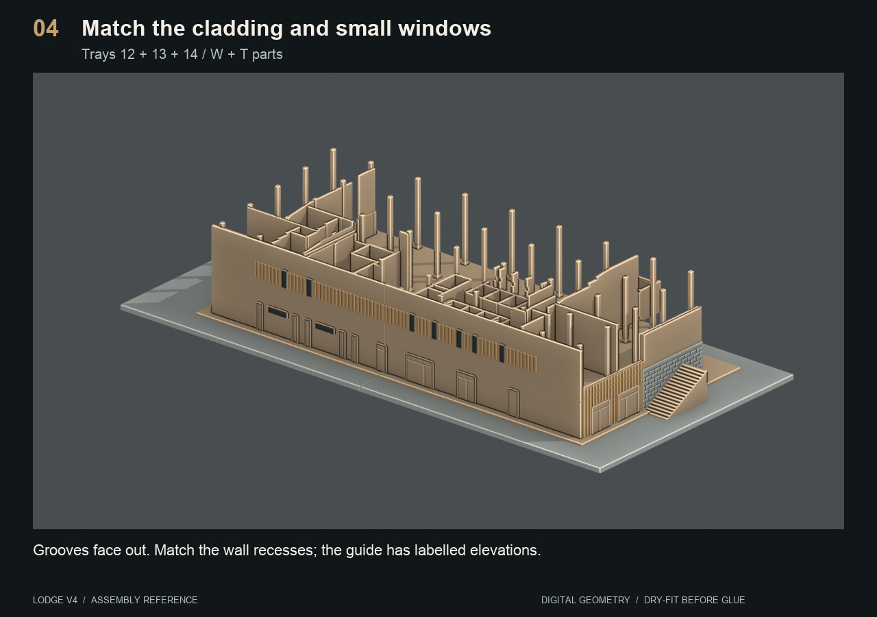
Fit the birch and gray skins to their matching recessed exterior patches, with grooves outward and flat backs toward the tan walls. Fit the small charcoal window inserts into the long solid west wall. Use the labelled elevations, exploded insert view and dimensions below. The digital render shows a thin tan skin in some lower pockets; check the actual print before fitting. If the pocket is open, dry-fit the dark insert. If only thin print flash covers the opening, carefully remove that film first. If it is solid wall rather than thin flash, stop and check the matching part before cutting. Do not force the insert or paint it to solve a fit problem. The exploded view shows all the actual dark loose pieces clearly. Dry-fit first, then bond these small parts where access is easiest.
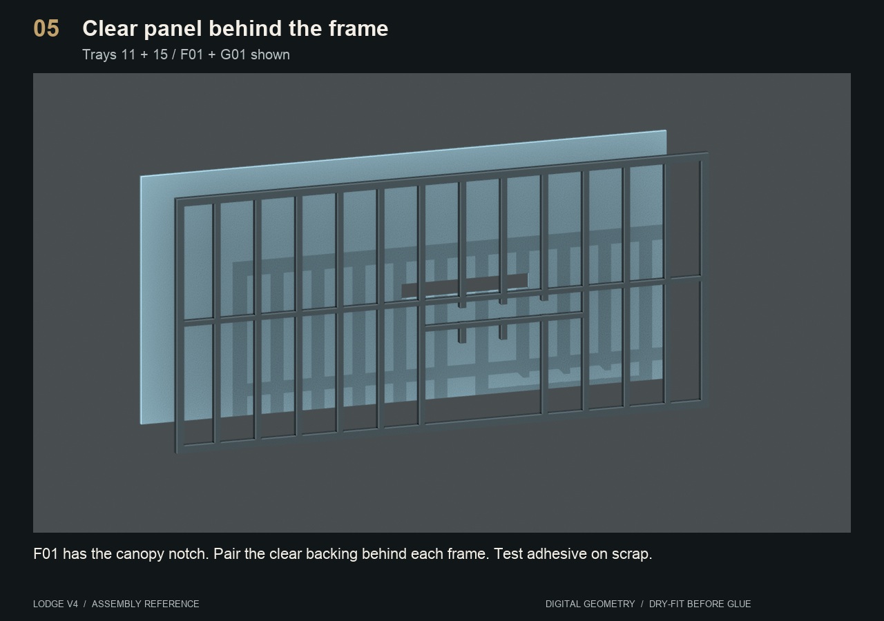
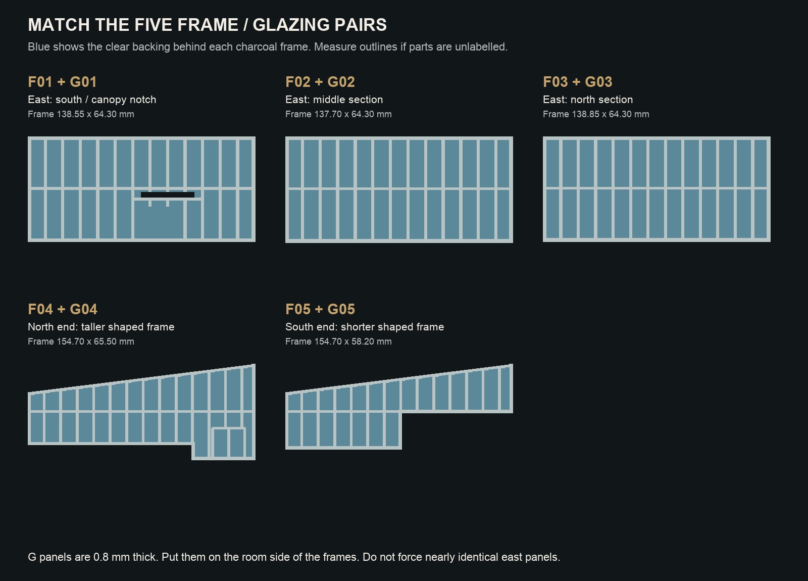
F01 is the long frame with the canopy notch, at the south end of the east side. Pair F01 with G01, F02 with G02, and so on. The clear panel belongs behind the charcoal mullions, toward the room. Three long frames are almost the same size, so compare their precise outlines and widths. Test your adhesive on scrap before touching the visible glazing; keep it off the visible face.
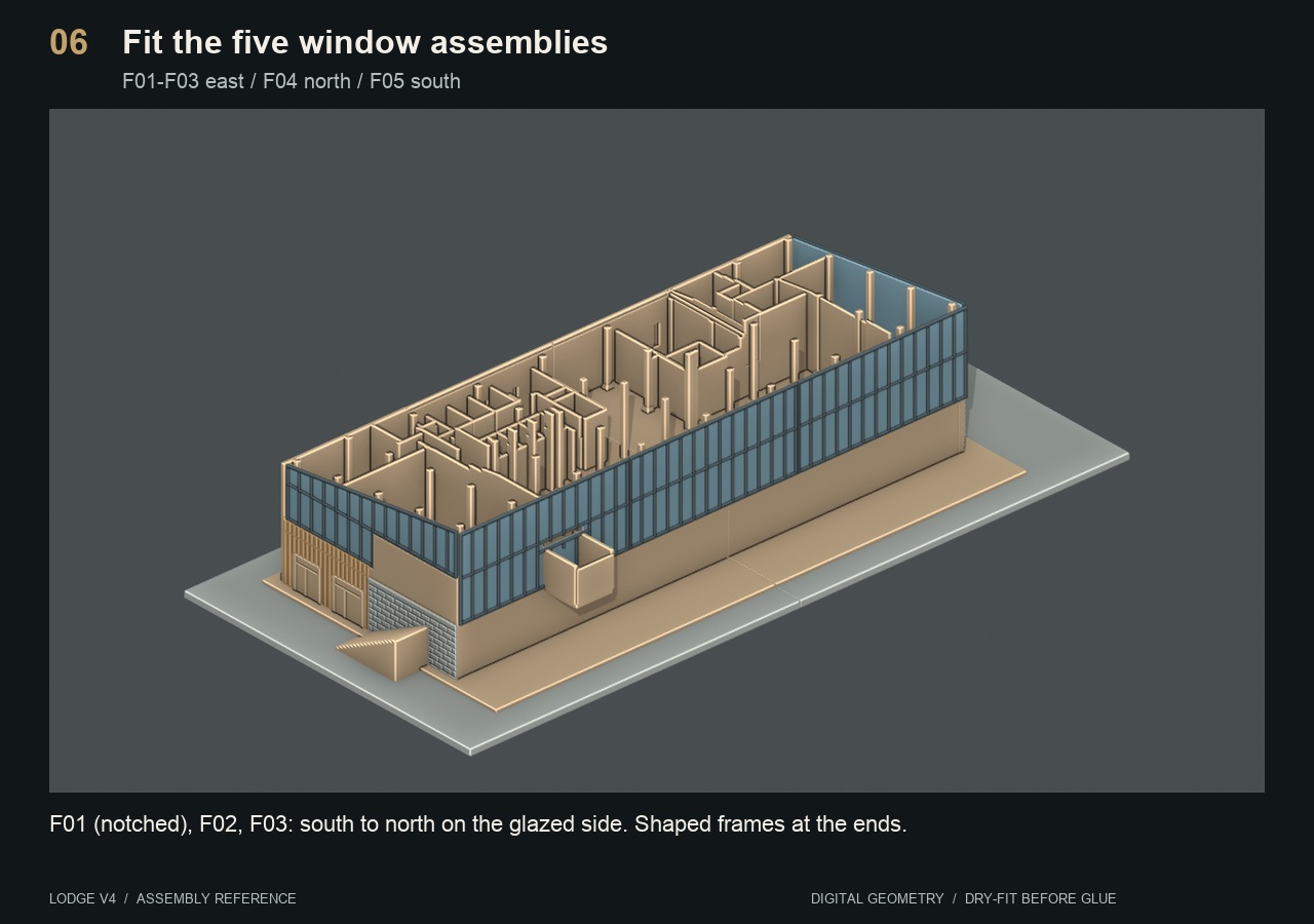
Start with the notched F01/G01 at the south end. Fit F01/G01, F02/G02 and F03/G03 along the long glazed east side, running south to north. F04/G04 is the taller shaped north end, and F05/G05 the shorter shaped south end. Hold the floor slab while seating them. Check both corner meetings and temporarily offer up the roof before bonding.
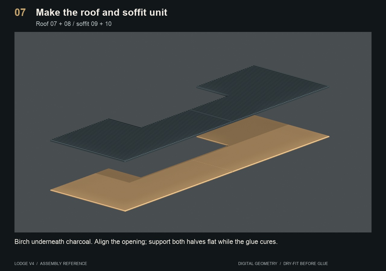
On the table, match the two charcoal roof halves and the two thin birch soffit halves. Birch belongs on the underside of the charcoal roof. Align the outer sloping outlines and the mechanical-equipment opening. The roof and soffit use butt seams, without floor-style tongues, and those two seams line up exactly. Support the unit flat in its own plane on a flat board, with gentle restraint at solid edges while the glue cures. Protect the ribbed top; do not press on thin projections. Their seam gap is intentional; hold everything flat and use the broad mating surfaces for bonding after the fit check.
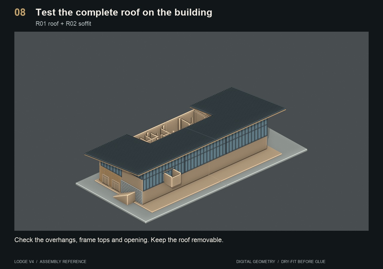
Lower the complete roof/soffit unit onto the building. Check that the frame tops are clear, the overhangs look consistent with the reference and the equipment opening is aligned. Leave this whole unit removable so the interior stays accessible. Lift it with one hand supporting each side of the seam. Do not rely on F02 or the rooftop equipment to hold separate halves together.
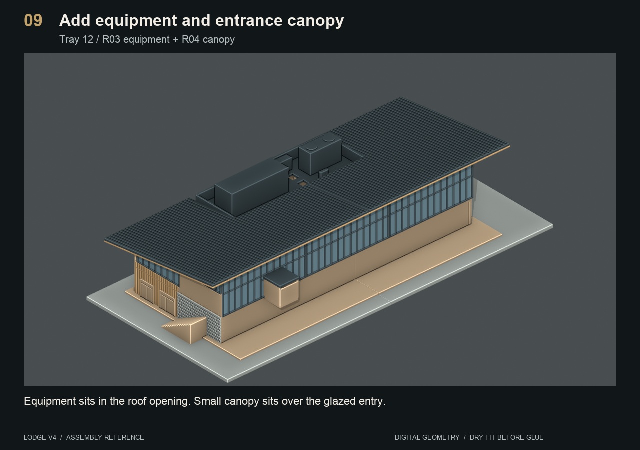
The large charcoal equipment block sits in the roof opening. The small separate charcoal canopy is the little square hood over the entry in the long glazed side, not an extra roof panel. Test both against the final picture before attaching. Keep adhesive away from anything that should remain removable.
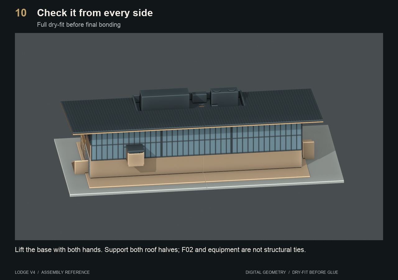
Look along the base and each floor seam, check the end frames, then lift the roof off and back on. The base seam should already be bonded and cured. Only after this remaining full dry-fit should you bond the other interfaces you want permanent. These renders explain the delivered geometry; your actual printed fit still decides where cleanup is needed.
Part IDs match the STL names and object names in the Bambu project. If you did not label the prints, compare the outlines, dimensions and neighbouring wall openings. Colours are the intended tray colours, not a requirement.
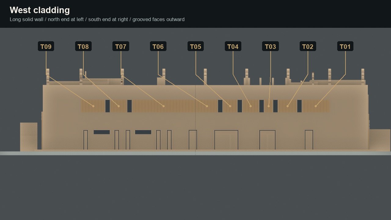
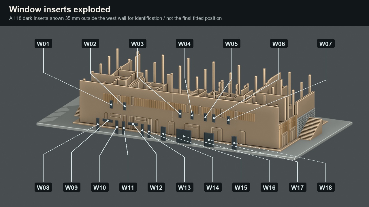
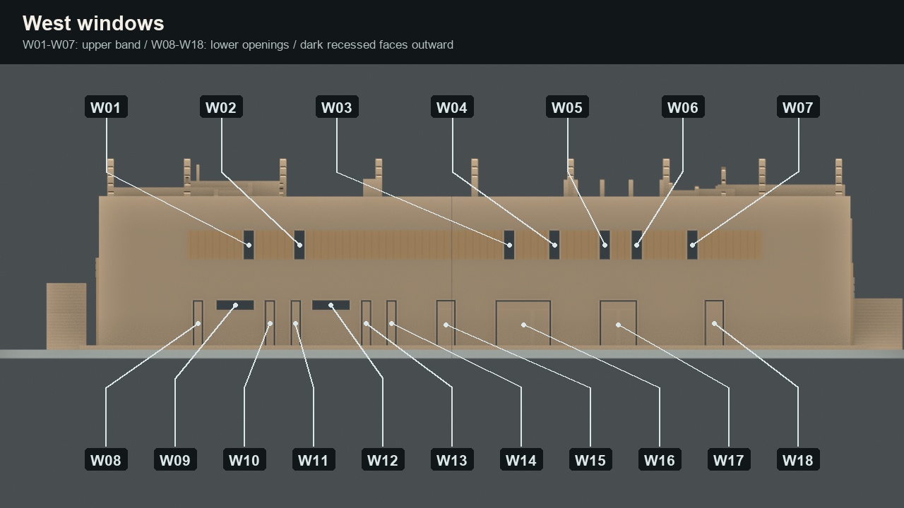
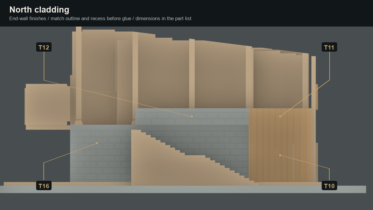
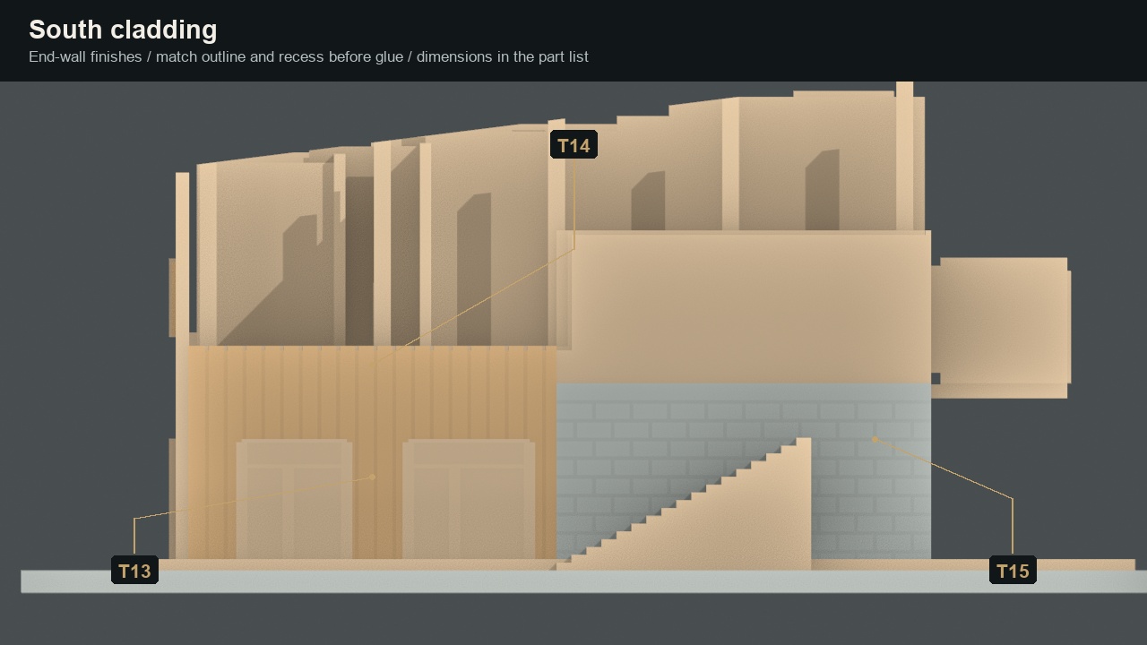
Dimensions in millimetres, in the saved print orientation. Compare the outline as well as dimensions.
| ID | Part / location | Print dimensions (mm) |
|---|---|---|
| T01 | T01 wood West wood veneer band 1 1 | 35.72 × 16.00 × 1.05 |
| T02 | T02 wood West wood veneer band 1 2 | 24.93 × 16.00 × 1.05 |
| T03 | T03 wood West wood veneer band 1 3 | 16.00 × 11.93 × 1.05 |
| T04 | T04 wood West wood veneer band 1 4 | 22.05 × 16.00 × 1.05 |
| T05 | T05 wood West wood veneer band 1 5 | 19.20 × 16.00 × 1.05 |
| T06 | T06 wood West wood veneer band 1 6 | 28.62 × 16.00 × 1.05 |
| T07 | T07 wood West wood veneer band 2 1 | 81.28 × 16.00 × 1.05 |
| T08 | T08 wood West wood veneer band 2 2 | 22.25 × 16.00 × 1.05 |
| T09 | T09 wood West wood veneer band 2 3 | 31.12 × 16.00 × 1.05 |
| T10 | T10 wood North lower wood entrance wall 1 1 | 41.45 × 40.00 × 1.05 |
| T11 | T11 wood North upper wood sill 1 1 | 41.45 × 10.85 × 1.05 |
| T12 | T12 stone North upper stone sill 1 1 | 74.40 × 10.85 × 1.05 |
| T13 | T13 wood South lower wood entrance wall 1 1 | 78.65 × 40.00 × 1.05 |
| T14 | T14 wood South upper wood sill 1 1 | 78.65 × 8.00 × 1.05 |
| T15 | T15 stone South lower stone wall 1 1 | 80.00 × 40.00 × 1.05 |
| T16 | T16 stone North retaining stone wall 1 1 | 117.20 × 40.00 × 1.05 |
Dimensions in millimetres, in the saved print orientation. Compare the outline as well as dimensions.
| ID | Part / location | Print dimensions (mm) |
|---|---|---|
| W01 | W01 dark window | 16.00 × 5.70 × 1.40 |
| W02 | W02 dark window | 16.00 × 5.70 × 1.40 |
| W03 | W03 dark window | 16.00 × 5.70 × 1.40 |
| W04 | W04 dark window | 16.00 × 5.70 × 1.40 |
| W05 | W05 dark window | 16.00 × 5.70 × 1.40 |
| W06 | W06 dark window | 16.00 × 5.70 × 1.40 |
| W07 | W07 dark window | 16.00 × 5.70 × 1.40 |
| W08 | W08 dark window | 25.90 × 5.70 × 1.40 |
| W09 | W09 dark window | 20.70 × 5.40 × 1.40 |
| W10 | W10 dark window | 25.90 × 5.70 × 1.40 |
| W11 | W11 dark window | 25.90 × 5.70 × 1.40 |
| W12 | W12 dark window | 20.70 × 5.40 × 1.40 |
| W13 | W13 dark window | 25.90 × 5.70 × 1.40 |
| W14 | W14 dark window | 25.90 × 5.70 × 1.40 |
| W15 | W15 dark window | 27.50 × 10.70 × 1.40 |
| W16 | W16 dark window | 30.70 × 27.40 × 1.40 |
| W17 | W17 dark window | 27.40 × 20.70 × 1.40 |
| W18 | W18 dark window | 26.00 × 10.70 × 1.40 |
Dimensions in millimetres, in the saved print orientation. Compare the outline as well as dimensions.
| ID | Part / location | Print dimensions (mm) |
|---|---|---|
| F01 | F01 east frame 1 | 138.55 × 64.30 × 1.80 |
| G01 | G01 east glazing 1 | 136.85 × 62.60 × 0.80 |
| F02 | F02 east frame 2 | 137.70 × 64.30 × 1.80 |
| G02 | G02 east glazing 2 | 136.00 × 62.60 × 0.80 |
| F03 | F03 east frame 3 | 138.85 × 64.30 × 1.80 |
| G03 | G03 east glazing 3 | 137.15 × 62.60 × 0.80 |
| F04 | F04 north frame 1 | 154.70 × 65.50 × 1.80 |
| G04 | G04 north glazing 1 | 153.00 × 63.69 × 0.80 |
| F05 | F05 south frame 1 | 154.70 × 58.20 × 1.80 |
| G05 | G05 south glazing 1 | 153.00 × 56.39 × 0.80 |
Dimensions in millimetres, in the saved print orientation. Compare the outline as well as dimensions.
| ID | Part / location | Print dimensions (mm) |
|---|---|---|
| B01 | B01 plinth S | 273.00 × 260.00 × 4.80 |
| B01 | B01 plinth N | 269.90 × 260.00 × 4.80 |
| B02 | B02 ground S | 252.21 × 213.00 × 36.80 |
| B02 | B02 ground N | 224.11 × 213.00 × 36.80 |
| B03 | B03 upper S | 224.81 × 192.67 × 69.06 |
| B03 | B03 upper N | 196.13 × 162.77 × 69.05 |
| R01 | R01 roof S | 259.06 × 202.18 × 3.35 |
| R01 | R01 roof N | 233.71 × 202.18 × 3.35 |
| R02 | R02 soffit S | 259.06 × 202.18 × 1.80 |
| R02 | R02 soffit N | 233.71 × 202.18 × 1.80 |
| R03 | R03 equipment | 214.82 × 73.47 × 38.71 |
| R04 | R04 canopy | 32.52 × 32.52 × 3.22 |
03 / THE PUBLIC PROJECT
Start with the V4 Bambu Studio project or the complete print kit. The Blender file contains the current V4 model. The native Fusion file is the earlier V3 study, clearly separated below.
Get the Ski Lodge on MakerWorld ↗
Download the STL kit and 15-tray project from MakerWorld, then open and slice in Bambu Studio using your actual printer and filament profiles. This release does not include a validated one-click Handy print profile.
V4 · 1:100
All 15 single-material plates, prepared for the H2S. Choose your own printer and filament profiles before slicing.
Download 260 KBV4 · 56 parts
Print-oriented STLs, assembled-position reference meshes, the Bambu project, test samples and print plan.
Download 985 KBV4 · native .blend
The current V4 assembly and visualization model, with materials and embedded geometry. Use the 3MF/STLs for millimetre print dimensions.
Download 473 KBV3 · earlier 1:200 revision
The earlier native Fusion source shown in the film. This is a source study, not the V4 print kit; its parts are not interchangeable with V4.
Download 508 KBSaved-profile layer and support choices. Match these to your printer and materials before slicing. The kit is arranged as separate single-material jobs.
| Tray | Parts | Material / colour | Layer | Supports |
|---|---|---|---|---|
| 01 - Gray plinth S | 1 | gray | 0.2 mm | No |
| 02 - Gray plinth N | 1 | gray | 0.2 mm | No |
| 03 - Tan ground S | 1 | tan | 0.16 mm | Yes |
| 04 - Tan ground N | 1 | tan | 0.16 mm | Yes |
| 05 - Tan upper S | 1 | tan | 0.16 mm | Yes |
| 06 - Tan upper N | 1 | tan | 0.16 mm | Yes |
| 07 - Charcoal roof S | 1 | charcoal | 0.16 mm | No |
| 08 - Charcoal roof N | 1 | charcoal | 0.16 mm | No |
| 09 - Birch soffit S | 1 | birch | 0.16 mm | No |
| 10 - Birch soffit N | 1 | birch | 0.16 mm | No |
| 11 - Charcoal facade cassettes | 5 | charcoal | 0.12 mm | No |
| 12 - Charcoal equipment canopy windows | 20 | charcoal | 0.16 mm | Yes |
| 13 - Birch timber cladding | 13 | birch | 0.16 mm | No |
| 14 - Gray stone cladding | 3 | gray | 0.12 mm | No |
| 15 - Clear PETG glazing | 5 | clear | 0.2 mm | No |
V4 3MF and STL dimensions are in millimetres. The Blender file is an assembly/visualization model. The Fusion V3 file is an earlier 1:200 revision and does not replace the V4 kit.
Download the project readme →